
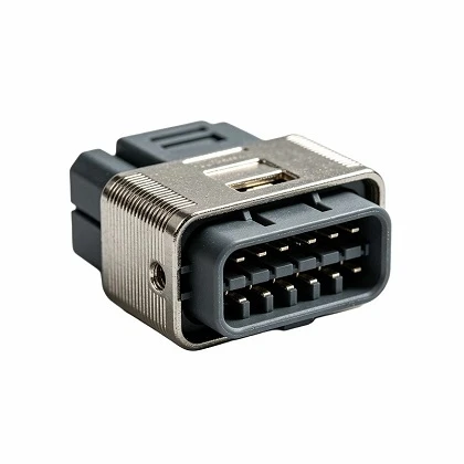
Electronic Module Positioning Components
Electronic Module Positioning Components | Custom CNC Machined Alignment & Mounting Hardware
Precision CNC machined positioning pins, PCB module alignment brackets, and industrial enclosure guide rails engineered for accurate registration, secure mounting, and repeatable positioning of electronic sub-assemblies in rack systems and automated equipment.
Electronic Module Positioning Components provide mechanical registration and structural stability for electronic sub-assemblies. Built for environments requiring high vibration resistance and tight spatial constraints, these components eliminate assembly drift, ensure precise connector mating, and streamline module replacement during maintenance.
Core Function: Mechanical alignment, positive locking, and thermal/electrical isolation for electronic modules.
Standard & Custom Configurations: Custom CNC positioning pins, locating bushes, snap-in brackets, and adjustable mounting rails.
Manufacturing Method: Multi-axis CNC milling, Swiss-turn machining, metal stamping, and precision injection molding.
Specifications
|
Parameter |
Specification Details |
|
Material Options |
Aluminum (6061-T6, 7075), Stainless Steel (304, 316), Brass, Engineering Plastics (POM, PEEK, PTFE) |
|
Dimensional Tolerance |
Up to ±0.01 mm (Achieved via high-speed CNC centers) |
|
Surface Treatments |
Clear/Color Anodizing (MIL-A-8625), Passivation (ASTM A967), Electroless Nickel Plating |
|
Thread & Fastener Types |
Metric (M2–M8) and Unified National (UNC/UNF) threads; helicil inserts available |
|
Operating Temperature |
-40°C to +125°C (Material dependent) |
|
Compliance & MOQ |
RoHS, REACH, ISO 9001:2015 certified; Low-MOQ supportive for pilot runs and production |
Features
High Positional Repeatability: Precision-machined registration surfaces maintain alignment within ±0.015 mm across repeated insertion cycles.
Vibration Resistance: Integrated locking features and spring-loaded retention pins prevent loosening in high-vibration mobile and industrial rack applications.
Galvanic Corrosion Prevention: Material pairings and surface conversion coatings prevent galvanic reactions when mounted to aluminum chassis or copper-grounded PCBs.
Tool-Less or Quick-Release Options: Ergonomic latching and quarter-turn configurations reduce module swap-out time in field service environments.
Materials & Manufacturing
Manufacturing relies on multi-axis CNC machining centers and automated stamping presses to ensure strict geometric dimensioning and tolerancing (GD&T).
Raw Material Sourcing: Certified mill test reports (MTRs) provided for all metal alloys, verifying chemical composition and tensile strength.
Machining Process: High-speed CNC milling and Swiss-type turning eliminate burrs and internal stresses, preventing warping after secondary finishing.
In-House Surface Finishing: Controlled anodizing and passivation lines ensure uniform coating thickness (10–25 μm for anodizing) and salt-spray corrosion resistance exceeding 500 hours.
Applications
Industrial Automation Controllers: Positioning and securing I/O module racks in DIN-rail and cabinet enclosures.
Telecommunications Chassis: Aligning high-density blade servers and power supply units within 19-inch racks.
Automotive Test Fixtures: Quick-align mounting brackets for ECU testing and sensor calibration rigs.
Medical Diagnostic Equipment: Precision guide rails for modular diagnostic cartridge insertion.
Customization
Custom engineering adapts components to specific mechanical interfaces and spatial constraints.
Dimensional Tailoring: Custom lengths, non-standard thread pitches, and modified flange dimensions based on STEP/IGES CAD files.
Material Selection: Custom alloy substitution for specific thermal conductivity, weight reduction, or non-magnetic requirements.
Laser Marking: Part numbers, batch codes, or client logos laser-etched directly onto components for traceability.
Quality Control
Inspection protocols verify compliance with engineering drawings prior to shipment.
Dimensional Verification: 100% first-article inspection (FAI) using CMM (Coordinate Measuring Machines) and optical comparator systems.
Surface Integrity: Eddy current testing and optical roughness gauges (Ra testing) monitor surface finish consistency.
Traceability: Lot numbers stamped on packaging enable full tracking from raw material batch to finished goods.
FAQ
Q: What is the typical lead time for custom positioning components?
A: Rapid prototyping takes 7 to 10 business days. Production runs typically ship in 3 to 4 weeks, depending on raw material availability and surface treatment requirements.
Q: Do you accommodate low-volume trial orders or prototypes?
A: Yes. We support low-MOQ pilot batches and functional prototypes to validate mechanical fits before mass production.
Q: Can you provide Material Test Reports (MTRs) and RoHS certificates?
A: Yes. Full material certificates and RoHS/REACH compliance documentation are included with every shipment or provided digitally prior to dispatch.
Q: What file formats do you accept for custom component RFQs?
A: STEP, IGES, SolidWorks (.sldprt), and PDF drawings with explicit GD&T tolerances are preferred.
RFQ
To request a quotation for standard items or custom electronic module positioning components, submit your requirements:
Required Documentation: 2D/3D CAD drawing with material specifications and tolerances.
Volume Requirements: Annual quantity, batch size, and target delivery schedule.
Contact Direct: Send specifications to our engineering sales team for a formal technical review and quotation within 24 hours.
Hot Tags: electronic module positioning components, China electronic module positioning components manufacturers, suppliers, factory
Send Inquiry
